[This is the web version of the paper published at SPIE 2020; Another crucial resource is the Science Case, available at the arXiv]. This paper has many authors (essentially the entire MAVIS phase A crew).
Abstract
A consortium of several Australian and European institutes – together with the European Southern Observatory (ESO) – has initiated the design of MAVIS, a Multi-Conjugate Adaptive Optics (MCAO) system for the ground-based 8-m Very Large Telescope (VLT). MAVIS (MCAO-assisted Visible Imager and Spectrograph) will deliver visible images and integral field spectrograph data with 2-3x better angular resolution than the Hubble Space Telescope, making it a powerful complement at visible wavelengths to future facilities like the space-based James Webb Space Telescope and the 30 to 40m-class ground-based telescopes currently under construction, which are all targeting science at near-infrared wavelengths. MAVIS successfully passed its Phase A in May 2020. We present the motivations, requirements, principal design choices, conceptual design, expected performance and an overview of the exciting science enabled by MAVIS.
1. Introduction
In June 2018, after an extensive, multi-year consultation with the ESO scientific and instrumentation community, ESO called for proposals to build a “wide” field diffraction limited visible instrumentation for the Adaptive Optics Facility at the Very Large Telescope. The MAVIS consortium was selected in November 2018 to do the Phase A for this instrument. The consortium was quickly and naturally put together during the bid period, composed of the Australian Astronomical Optics (AAO), specifically AAO-Stromlo (ANU) and AAO-MQ (Macquarie University), the Istituto Nazionale di Astrofisica (INAF), specifically the nodes of Arcetri, Padova, Roma, Milano and Capodimonte, the Laboratoire d’Astrophysique de Marseille (LAM), and the European Southern Observatory (ESO, both customer and consortium member).
The call for proposal stemmed from a consultation process to the ESO science community, which concluded that a “wide field, AO-corrected instrument, providing imaging and spectroscopic capability” was of high interest for the next generation of facility instrument for the VLT AOF. Is it a testament to how far and how mature Adaptive Optics (AO) has come that we can now consider building such a facility, providing about 125nm of wavefront error - and 18mas FWHM - in all directions within a field of view of 30” in diameter, thereby allowing for the first time ground-based wide-field diffraction limited imaging and spectro-imaging in the visible. This is a part of the wavelength/angular resolution domain that has never been offered before; It enables a wide variety of exciting science cases [McDermid 2020], which are briefly exposed in Section Science.
MAVIS includes three main modules: The AO bench, an imager and an IFU spectrograph. The science wavelength covers 370-950nm. The imager is using a 4kx4k CCD at 7.36mas/pixel. It includes the standard broadband, and a number of narrow band filters. The IFU has two spatial sampling modes (20-25 and 40-50 mas/spaxel) and four spectral modes. The main characteristics of the AO module and the two instruments are presented in Table 1 below. MAVIS requirements are given in Section Requirements, the system design is presented in Section Design, and its expected performance in Section Performance.
| Parameter | Value |
|---|---|
| General Properties - AO Module | |
| Focus | Nasmyth A VLT-AOF (UT4) |
| NGS Field of View | 120” diameter disk |
| Number of NGS | ≤ 3 |
| Limiting magnitude | Hmag ≥ 18.5 |
| LGS beacons | 8 on a circle of 17.5” ⌀ |
| Sky coverage | ≥50% at the South Galactic Pole |
| Ensquared Energy | > 15% within 50mas at 550nm |
| Strehl | > 10% (15% goal) in V-band |
| Imager | |
| Field of View | 30” x 30” |
| Pixel Scale | 7.36 mas/pix |
| Sensitivity | V > 29mag (5σ) in 1hr |
| Filters | BVRI, ugriz, various narrow bands |
| Spectrograph | |
| IFU Spaxel Size and FoV #1 | Fine Sampling: 20-25mas spaxels, 2.5” x 3.6” FoV |
| IFU Spaxel Size and FoV #2 | Coarse Sampling: 40-50mas spaxels, 5” x 7.2” FoV |
| Spectral Configuration LR-Blue | 5,900 resolution, 370-720nm, 21@550nm |
| Spectral Configuration LR-Red | 5,900 resolution, 510-1000nm, 21.5@750nm |
| Spectral Configuration HR-Blue | 14,700 resolution, 425-550nm, 19.6@475nm |
| Spectral Configuration HR-Red | 11,500 resolution, 630-880nm, 20.7@725nm |
The Phase A was kicked off on February 1, 2019, and after 15 months of studies, led to a review in May 2020. The review was successful, and approval for construction is currently following the regular process through the Science and Technical Committee, Finance Committee and Council at ESO. Assuming Phase B starts early 2021, the current schedule puts the commissioning in the first semester of 2027, roughly in line with the ELT first light. The project status is discussed in Section Status.
2. Science Case
The MAVIS science case is publicly available at the arXiv [McDermid et al 2020]; we encourage the reader to look at it for more details on the wide variety and scientific relevance of the proposed programs.
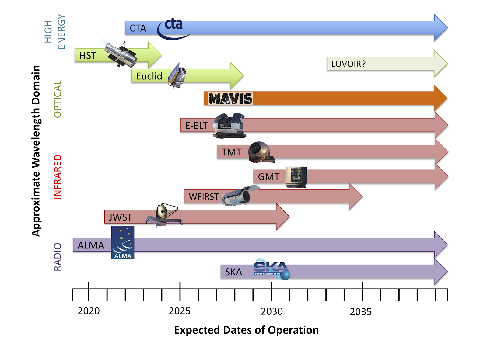 Fig 1: Overview of facilities operating on the timescale of MAVIS
By the second half of this decade, the need for a general purpose instrument able to provide optical imaging and spectroscopic capabilities at <100mas angular resolutions, with the light-gathering capability of an 8m-class telescope, will be urgent. JWST will be completing its 5-year design mission length, with potentially another 5 or more years ahead, having opened a new window on how stars and galaxies form in the first few hundred million years of the Universe, and revealed the formation process and atmospheric properties of planets around other stars. GAIA will have completed its precision astrometry census of the Milky Way, mapping the positions, distances and 3D motions of over a billion stars (as well as many millions of other sources) with unprecedented accuracy. ALMA will be into its second decade of discoveries, potentially upgraded for higher survey speed, and considering longer baselines for higher angular resolution (≈10mas) studies. The Hubble Space Telescope, after opening the eyes of generations of scientists and the public alike to the beauty and complexity of the Universe when seen without the distortion of Earth’s atmosphere, will very likely be non-operational. However, collection of near-HST resolution optical-infrared imaging for a third of the extragalactic sky will be underway through the Euclid and WFIRST space-mission surveys, providing uniform high-resolution images to depths of ≈25th magnitude. The E-ELT (and other new ELT facilities) will be seeing first light, making commonplace a regime of faintness and angular resolution at infrared wavelengths that has never been explored before.
A common theme among each of these exciting new developments is the ability to look deeper and sharper than ever before at the complex physical processes that underpin the observable Universe. A notably missing element, however, is a flexible, PI-driven facility instrument on a large-aperture telescope that will support, contribute to, and lead this new regime at optical wavelengths. MAVIS addresses this need, capitalising on the large investment of technology and experience in the VLT Adaptive Optics Facility to provide an efficient and stable platform for high-resolution optical astronomy into the next decade.
The principal innovation of MAVIS is to deliver a large, AO-corrected field of view with an image quality close to the diffraction limit of the VLT at optical wavelengths, across the vast majority of the sky. Working at such high angular resolution (≈18mas) utilizing the large collecting area of the VLT will be groundbreaking for a broad range of exciting science. Importantly, the unprecedented sky coverage of MAVIS means that, for the first time, we can consider such a capability in the context of a general-purpose facility instrument. As such, MAVIS combines imaging and spectroscopic capabilities designed to address a broad range of science goals in a unique and competitive manner, while at the same time, providing stable, robust and efficient science operations.
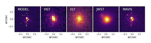 Fig 2: Example of a morphological study of an high-z galaxy as observed with HST, ELT-MICADO, JWST-NIRCam and MAVIS in I band. Based on the z=5 high resolution simulated "Althaea" galaxy (Pallottini et al. 2017), shown in the first panel. The other panels show instead how the same target of 25 AB magnitude would appear in I-band if observed with different facilities for a fixed exposure time (1h). In the VLT/MAVIS image, clumpy regions as faint as 29th AB mag are detected with a signal-to-noise-ratio 5.
MAVIS will allow the deepest optical images ever obtained for point sources and compact galaxies. For example, MAVIS will detect sources 1 full magnitude deeper than the Hubble Ultra Deep Field (30.4mag vs 29.4mag around I band), but using 1/10th of the exposure time (10hr vs. ≈100hr). At the same time, the spatial morphological information from MAVIS will exceed any existing facility at these wavelengths, including ELTs and JWST, allowing both the faint-end of the UV luminosity function at z>7 to be probed together with UV morphologies at this epoch.
On the other side of “cosmic noon”, MAVIS will combine spatial and spectral resolution to untangle the gravitational and feedback-driven motion of gas in the ISM of disk galaxies over the past 8 billion years. This is crucial to understanding the formation of Milky Way-like galaxies, and to physically connect the turbulent clumpy galaxies seen at early epochs with the relaxed and regular morphologies we see today.
In the local volume (<100Mpc), MAVIS will be transformative to our understanding of physical processes within galaxies - the so-called “sub-grid physics” that collectively represents the greatest obstacle to building a complete understanding of galaxy evolution. By the mid 2020s, simulations of galaxy formation will be reliably predicting <=100pc-scale phenomena in cosmological volumes. MAVIS will provide essential constraints on these scales within a similar local volume, crucially providing rich spectroscopic data sets with which accurate gas, dust, and stellar population diagnostics can be obtained on <10pc scales.
The exquisite sensitivity and angular resolution of MAVIS, coupled with the rich diagnostic power of optical colours, will revolutionise the study of stellar populations in galaxies beyond the local group by enabling precise photometry of individual stars at distances of up to 10Mpc, enlarging the volume available for such analysis by orders of magnitude. This will break new ground in understanding the stellar populations of galaxies with diverse formation and evolutionary paths, and provide access to unexplored regimes of low surface brightnesses inaccessible to integrated light spectroscopy. Importantly, the angular-scale and flux regime of MAVIS at optical wavelengths is very well matched to that of MICADO on the E-ELT, creating a powerful synergy of colour diagnostics from V through K bands, significantly improving the diagnostics possible with either facility alone.
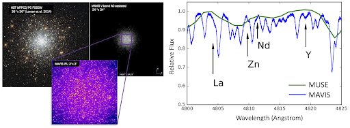 Fig 3: Left: HST observations of a globular cluster in the Fornax dwarf spheroidal galaxy, compared with simulated observations of MAVIS V-band, with a zoom on the central regions (FoV≈3" , corresponding to the MAVIS spectroscopic mode). Right: Small section of a MAVIS HR-Blue spectrum (blue line, R≈15000), with several neutron-capture elements labelled. For comparison, the same spectrum as observed with MUSE (R≈1900) is overplotted in green.
Spectroscopically, MAVIS will also probe new extragalactic environments for stellar populations. At large distances, only the most massive stars are bright enough for spectral metallicity and abundance studies, and these typically live in crowded star clusters which have not yet dispersed. MAVIS uniquely combines spatial and spectral capabilities to explore these regions, either on individual stars directly, or exploiting MAVIS-derived colour-magnitude selections for accurate stacking analyses.
MAVIS will play a significant role in bridging the observational gap in mass between black holes formed from individual stellar mergers (10–100 M☉ from recent gravitational wave detections) and the so-called “supermassive” black holes (106–109 M☉) thought to play a decisive role in the growth and evolution of galaxies, yet whose formation process is completely unknown.
At the upper end of this gap, MAVIS will observe statistical samples of low-mass galaxy nuclei with sufficient spatial and spectral resolution to confidently constrain the presence of 105–106 M☉ black holes using integrated light spectroscopy, and at the same time shed light on the evolution of the host systems (Stripped large galaxies? Or relic nuggets from the early Universe?).
At the lower end of the black hole mass gap, the innovative transmissive design of the MAVIS AO Module will allow precision multi-epoch astrometry in the densest regions of Milky Way globular clusters, which are too crowded for HST or GAIA astrometry, yet are the best hunting grounds for the elusive “intermediate-mass” black holes (103–104 M☉). MAVIS will allow tens of clusters to be probed on relevant scales, building a firm statistical basis for the presence, or not, of IMBHs, with either outcome having profound implications.
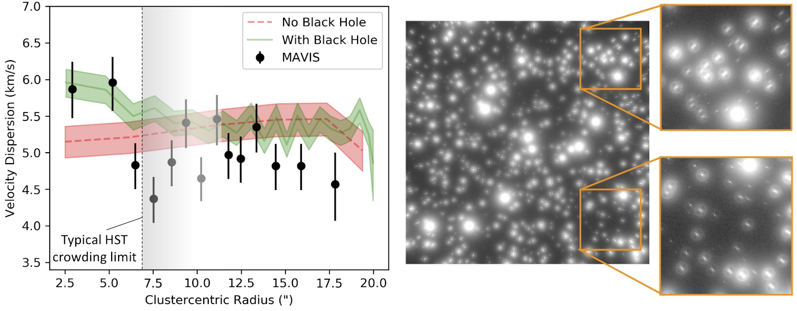 Fig 4: Simulation illustrating that even in the presence of a complex MCAO PSF, accurate proper motions can be derived at the precision, depth and radius required to detect the presence of an intermediate mass black hole at the centre of a Milky Way Globular Cluster, overcoming the typical confusion limit that hinders HST\cite{monty2020-1}
The dense central regions of globular clusters are also unexplored regimes for understanding the chemical and dynamical evolution of these once-called “simple stellar populations”, yet whose properties continue to defy explanation by current models of cluster formation, evolution or stellar nucleosynthesis. Tackling these issues cannot be done with imaging alone, nor by considering simple scaled-solar total metallicities, even if from individual star measurements. Understanding these evolved stellar systems requires a comprehensive abundance analysis across multiple nucleosynthetic channels, coupled with high-precision radial velocity information to understand the role and demographics of binary stars. This is exactly the capability that MAVIS will provide, giving a significantly higher spectral resolution and bluer wavelength coverage than any existing facility, opening access to precision elemental abundances in environments where they are most unknown.
MAVIS will also probe the immediate environments around individual stars, revealing the processes driving angular momentum loss that ultimately shapes star and planet formation, and probing the later stages of stellar evolution through mass-loss, re-formation of second-generation protoplanetary disks, and exploration of white dwarf binaries as the progenitors of Type Ia supernovae. In the circumstellar environment of our own star, the large sky coverage and flexible guide configurations of MAVIS will provide a new capability of on-demand and time-sensitive observations for minor bodies within (or passing through) the Solar System, as well as allowing regular monitoring of major bodies at 10s-100s km resolution.
3. System Requirements
Initially generated by ESO and then re-worked by the MAVIS consortium during the Phase A, the very top level requirement specifications for scientific capabilities can be summarised as follow:
- Strehl ratio: Under standard Paranal turbulence conditions (0.87” seeing at 500nm, which corresponds to 0.8” seeing at zenith and a 30 degrees zenith angle), MAVIS shall provide V-band Strehl ratio ≥ 10% (goal 15%) anywhere over the science field, with a relative Strehl ratio variation of less than 10% over the science field of view.
- Sky coverage: MAVIS, in at least 50% of random pointings within 10 degrees of the Galactic pole, shall provide AO correction leading to ensquared energy, in V band, of at least 15% within a 50 mas square aperture - this actually corresponds to a 50% loss compared to the best NGS case.
- Wavelength range: MAVIS shall provide imaging and spectroscopic capabilities from 370-950nm (goal 370-1000nm).
- Imaging field of view: MAVIS shall provide an unvignetted science field of view of at least 30×30 arcsec - the Strehl performance requirement applies on a disk of 30” diameter.
- Imaging sensitivity: MAVIS, in a one hour total exposure time, shall be able to image an isolated point source of mV=29 with a SNR≥5.
- Astrometric performance: MAVIS, assuming on-image reference sources are present to enable the plate-scale and rotation calibration to at least 0.01%, shall enable astrometric measurements such that the relative position of two unresolved, isolated sources, detected with an SNR>200, separated by up to 1 arcsecond, can be measured to within 150 μas (goal 50 μas).
- Spectrograph field of view: MAVIS shall provide spectroscopic capabilities over a field of view area of at least 9 square arcsec.
- Spectroscopy Spectral Resolution: MAVIS shall provide four spectroscopic spectral resolution configurations, as follows:
- LR-Blue: A mean resolution of R>5000 over 370-720nm
- HR-Blue: An minimum resolution of R=12000 over 425-550nm
- LR-Red: A mean resolution of R>5000 over 510-950nm (goal 510-1000nm)
- HR-red: An minimum resolution of R=9000 over 630-880nm
- Spectroscopy Spatial Resolution: MAVIS shall support two spectroscopic spatial configurations:
- Fine sampling: 20-25 mas square spaxels;
- Coarse sampling: 40-50 mas square spaxels;
In addition, there are of course a number of operational, lifetime and ESO-standard related requirements. Notable are the requirements to operate on non-sidereal targets or guide stars, need to provide PSF reconstruction and a 2 airmass maximum zenith operation distance.
4. Design Overview
 Fig 5: MAVIS field schematic layout
Informed by a number of trade-off studies on the most critical elements, the MAVIS design went through several iterations during the pre-Phase A and the Phase A to finally coalesce on the design presented at the Phase A review. The considerable expertise from the consortium in adaptive optics and post-focal instrumentation helped in converging toward a healthy design, which maximises throughput, minimises optical aberrations while allowing easy alignment and modular integration. The companion paper from Viotto et al [2020] and Ellis et al [2020] give more details about the AOM and instruments design and characteristics.
In a few top level bullets, the current MAVIS design can be summarised as follow:
- A largely transmissive design across the board (AOM, imager, spectrograph);
- Two post focal DMs totalling about 4250 actuators (5420 including the DSM);
- Eight Laser Guide Stars, feeding eight 40×40 Shack-Hartmann wavefront sensors, created from splitting the four existing AOF lasers;
- Three near-infrared natural guide star wavefront sensors, also providing focus (each NGS WFS has a selectable 1×1 or 2×2 lenslet array);
- An imager covering the 30 arcsec field of view, Nyquist sampled in V band (7.36mas/pixel);
- A very compact, high throughput monolithic IFU-based spectrograph, covering 370 through 950nm (goal 1000nm), with four spectral modes, providing spectral resolutions from 5000 through over 10000 and two spaxel scales (25 and 50 mas/spaxel), corresponding to field of view of 3.6”×2.5” and 7.2”×5” (see Table 1).
In the following, we detail the most important subsystems.
4.1 Splitting the Light
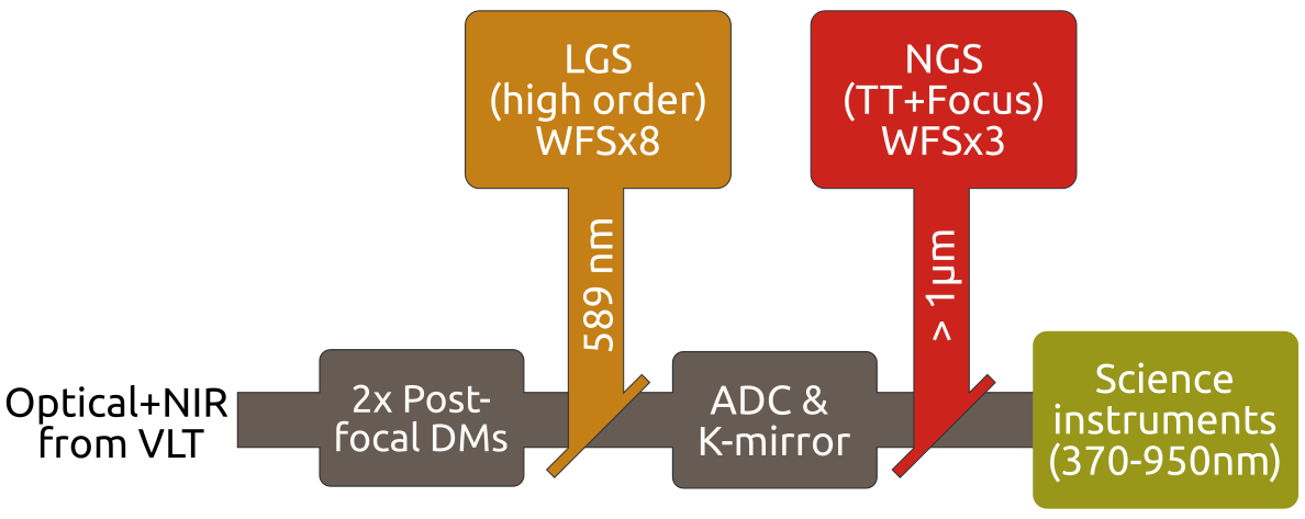 Fig 6: Guide star pick up cascade and wavelength split.
Figure 5 gives a schematic of the field organisation: the technical field, imager and IFU, as well as the location of the laser and natural guide stars. Note that because the split NGS/Science is done on a wavelength basis, the NGS can be anywhere inside the technical field, including within the science field. Similarly, the LGS split is also done with a dichroic, so there is no shadow from pick up mechanisms, as illustrated by Figure 6.
4.2 AOM Optical Design
The design is optimised on providing the best performance in the core domain of operation, i.e. V through I band, but can be operated with good performance down to U band and up to z band. Figure 7 gives a snapshot of the AOM optical design. The core, active part of the AO module is extremely compact (≈1x1.5m). The AOM and all its enclosed mechanisms are gravity invariant, and will be enclosed into a passive thermal enclosure, making it relatively stable (at least over a period of a few days) and thus reducing the need for recalibration and look up tables. For more details, see the companion paper on the AOM optical design [Greggio et al 2020a], and the one dedicated to the innovative ADC three-glass design [Greggio et al 2020b].
 Fig 7: Adaptive optics module optical design
4.3 Instruments
Imager
The imager covers the whole optical region and includes two filter wheels which accommodate 7 broadband, 15 narrow band and 5 neutral density filters. It covers a field of 29.5×30.2 arcsec with pixels of 7.36 mas, using a CCD-250 with 10 micron pixels. The CCD is directly at the output focus provided by the AOM, which avoids the need for re-imaging optics, again maximising throughput.
Spectrograph
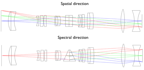 Fig 8: Spectrograph Optical Design (one of the two identical units), excluding the image slicer in both spatial and spectral directions.
Because it is fed by a diffraction-limited beam, the spectrograph is very compact. It has two identical units, each of them covering half of the field of view. Each unit provides four different spectral configurations, as well as two sampling/field of view, as listed above and in Table 1. Various innovative and more classical solutions were investigated for the image slicer. The slicer is certainly one of the most challenging and costly single element in the whole instrument (with the possible exception of the DMs), thus significant efforts have been made to optimise it. This results are reported in a dedicated paper [Content et al 2020]. Currently we have retained a two-mirrors solution, although this will likely be revisited during the MAVIS Phase B.
To provide the necessary sampling for the spaxels, at the given spectral resolution, we need large CCDs; we have retained e2v CCD290-99 (one per spectrograph, i.e. two CCDs) as our current baseline, with slightly more than 9k×9k pixels, at 10 microns/pixel.
The imager and spectrograph are covered in details in a companion paper [Ellis et al 2020].
The initial set of MAVIS science White Papers included a number of science cases that would benefit from instrumentation with different capabilities in addition to the MAVIS baseline imager and IFU spectrograph. This drove us to include a third port in the design, allowing for possible future instruments to take advantage of the unique MAVIS AO-corrected beam.
4.4 Nasmyth Integration
Figure 9 gives an impression of how MAVIS will fit on the UT4 Nasmyth port. It is a multi-tiered design, with the LGS (orange) and NGS WFSs (red) underneath the main AOM bench (yellow). The instruments (imager in dark blue, spectrograph in pink) are located toward the outer edge of the platform, with the direct feed being directed to the imager. A Calibration unit (in green) is located close to the input focal plane, and provides a full calibration facility -to the exception of a turbulence simulator and a DSM simulator- for both the AO module and the instruments. Finally, MAVIS has designed-in a third instrument port (turquoise). The current design provides good access to all sub-modules for maintenance and installation.
 Fig 9: Mechanical overview of MAVIS on the Nasmyth platform.
4.5 Performance and AO Dimensioning
The current design meets and often exceeds the ESO Top Level Requirements. MAVIS is very ambitious and there is very little margin, in terms of design, to reach the performance specifications. After investigating a broad range of technical solutions, we have retained one which appears the least risky while providing the desired (maximum) performance.
The performance of the system as designed can be summarised as follow:
- V band Strehl > 10% under the ESO typical turbulence conditions (0.87” seeing). This drove AO system design, including the number of DMs, number of actuators, given the requirement on science field of view. This number includes AO residuals as well as alignment, NCPAs and manufacturing errors;
- 50% sky coverage for 15% encircled energy within a 50mas spaxel. Experience shows that the sky coverage is of the utmost importance in the exploitation and success of a high angular resolution instrument like MAVIS. We adopted a no-compromise approach, using SAPHIRA near infrared electron-multiplied arrays that provide state of the art sensitivity. Natural guide star (Tip-Tilt and low order modes) is done in the near-infrared, providing extremely well compensated images (15 to 80% Strehl ratio) and access to the full 120” diameter technical field of view. The NGS assembly includes three NGS WFSs to compensate for both Tip-Tilt and plate scale modes at high frequency (up to 1kHz). Each NGS WFS can also select a 2×2 Shack-Hartmann mode, providing focus and astigmatism measurement that can be used to control focus drift from Sodium layer altitude changes, and some degree of monitoring of NCPA drifts.
It was realised early into Phase A that four laser guide stars were not enough to limit the tomographic error to reach the specified error budget. As part of the many trade-off studies, solutions with 4, 6 and 8 LGSs were compared. The 8 LGS solution was clearly a winner overall; The 8 LGS are created by splitting the existing 4 LGSF lasers using simple, yet efficient (>93%) diffractive gratings. This in turns means that only about half the power is available per beam compared to the current LGSF situation - which fortunately is very comfortable. We have run many numerical simulations and confirmed that, with the low noise of the CCD220, we can deal with almost every condition of sodium return. Only in the lowest abundance months (Jan-Feb) will there be periods during which operation will only be possible with reduced performance (by running the LGS loop slower or using alternative techniques exposed later in this paper).
MAVIS is a multi-conjugate AO system. As such, it requires tomographic techniques to drive the deformable mirrors in order to maximise performance over the corrected field of view. AO control is currently a hot topic in the MAVIS consortium, with interesting cross-fertilisation between the INAF (lots of experience and also responsible for MAORY AO control) and the ANU/AAO-Stromlo teams; new methods have emerged that appear to boost MAVIS performance with respect to more classical tomographic controller, and that could also benefit MAORY (e.g. Learn and Apply, non-split tomography, simple prediction method implementation, Tikhonov regularisation, optimised control laws, etc).
4.6 Real-Time Controller
The Real-Time Controller [Gratadour et al 2020] is absolutely central in being able to implement these optimal AO control methods. Typically, 8 CCDs (240×240 each) have to be read at 1kHz, feeding all these pixels for processing, centroid calculations and eventually to be used to estimate DM control through a matrix-vector multiply with an approximately 20000×5500 matrix, with a pure RTC latency requirement of 250 microseconds. This is challenging, but has already been demonstrated by our team, at specification, using COSMIC (COmmon Scalable and Modular Infrastructure for real-time Control), the GPU-based approach developed in the past 5 years at observatoire de Paris, starting with the Green Flash project and now supplemented by the team at ANU [Ferreira et al 2018].
4.7 Instrument Control System
The ICS is under the responsibility of the INAF team that has delivered a number of previous ICS for VLT instrument. MAVIS, but also all incoming VLT instrument, have now to follow ELT s/w and h/w standards [Salasnich et al 2020].
4.8 AIVT and Commissioning
Operation considerations are important in AO, and especially in Laser AO. Care has been taken in the design to minimise the need for look up tables and calibrations: Drawing from the experience with e.g. GeMS at Gemini [Rigaut et al 2013, Neichel et al 2014], we know that these are very chronophage during commissioning. Operation and acquisition are also complex with tomographic LGS AO systems. Fortunately, MAVIS will be installed on the AOF, which has paved the way in reducing AO operational overheads. Generally speaking, it is a blessing for MAVIS to go on such a well known and performant platform as the AOF, including the DSM, LGSF and operational experience.
Integration and testing will be challenging for MAVIS, if nothing else because the geographical spread introduces new –but not unknown– constraints. The concept for the global sequence of the MAIVT is to have modules and sub-modules assembled and tested at the facilities of the responsible institutes. A performance verification and internal review will be performed before shipment for the global instrument integration and testing. The final system integration and verification of MAVIS will be done at ANU/AAO-Stromlo (Preliminary Acceptance Australia).
5. Expected Performance
5.1 AO Simulations
The MAVIS performance requirements are for the so-called typical Paranal atmospheric conditions. Consequently, all simulations were done for a seeing of 0.80” (zenith, 500nm) and a zenith angle of 30 degrees (so, overall, a seeing of 0.87” in the line of sight).
Several tools were used to estimate the MAVIS performance presented in this section. PASSATA\cite{Agapito_2016}, an AO simulator developed at INAF, was used to generate most of the end to end results. We also used a Fourier-based code as well as a set of various software tools to quickly estimate the sky coverage and the overall error budget. All of these tools have been developed, tested and debugged within the MAORY design studies; they are readily applicable to MAVIS. Additionally, we also used COMPASS [Ferreira et al 2018] and Yao [Rigaut & van Dam 2013], providing redundancy and complementarity (some simulation features are only available on some platforms). Agapito et al [2020] give a complete report of the simulation results.
The numerical simulations were used for two main purposes: Dimensioning the system, and predicting performance. System dimensioning was done primarily with the Fourier code at Arcetri and LAM, as well as PASSATA. Dimensioning the system required answering the following questions:
 Fig 10: Generalised fitting error as a function of the altitude of DM2 (abscissa) and DM3 (ordinate).
- How many post-focal DMs are needed? What altitude should they be conjugated to? It turns out that two post-focal DMs are enough to drive the generalised fitting error down to <25nm (for the particular ESO Paranal canonical Cn2 profile), as shown in Figure 10; As the figure shows, we have some margin in selecting the Dm conjugation: we choose to conjugate at 6 and 13.5 km above ground.
- How many LGS are needed to drive the tomographic error down to a value compatible with the MAVIS Strehl requirements? Simulations showed clearly that 4 LGS are not suitable, as it results in a tomographic error that takes, by itself, almost the entirety of the error budget (≈110nm). We concluded that 8 LGS was the correct number, which was deemed superior to 6 LGS for a variety of reasons. Note that these 8 LGS are obtained by splitting the 4 LGSF lasers. 8 LGS is also always better than 6, even considering the additional noise due to the split. The LGS are on a circle of radius 17.5”.
- Regarding the noise: We used the extensive AOF database of sodium return over the last 2-3 years to investigate what fraction of the time the system will be limited by the low number of photons back from the sodium layer. We found that, even though the LGSF return is quite high, we will feel the impact of low return on a significant fraction of the time (up to 30%) in the low sodium column density months (local summer). We are investigating several avenues to mitigate this issue, like increasing laser power, predictive control, or super-resolution, achieved by introducing differential rotation or misregistration in the LGS WFS. The latter could allow the use of lower resolution WFS (e.g. 32×32), thereby improving the photon count per subaperture.
- How many subapertures and what actuator pitch? The success and experience of the AOF LGS WFS (40×40) is a strong incentive to not depart from this design, unless we find compelling reasons to. We found that 40×40 was indeed providing the best results, and adopted pitches of 25cm and 32cm for the 6km and 13.5km DM respectively. The DSM has 1170 actuators, on a non-cartesian geometry, but roughly equivalent to a pitch of 22cm. Fitting error is the dominant term -with tomographic error right behind it- at about 70nm (for the Paranal Cn2 profile and seeing of 0.87”). We toyed with the idea of supplementing the DSM with a higher density ground conjugated DM within MAVIS, but it was not absolutely warranted, and was a very expensive proposition.
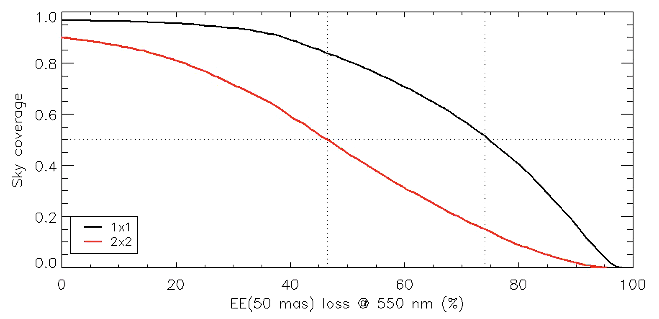 Fig 11: Equivalence between Sky Coverage at the South Galactic Pole and loss of EE (50mas) at 550 nm with respect to the AO-corrected PSF without jitter (note that a loss of 50% with respect to the nominal performance correspond to 15% absolute EE in the same 50mas spaxel).
- Sky coverage and designing the NGS WFS: MAVIS is unusual in the sense that it does its science in the visible, and thus the NIR is left and can be used for the TT sensing. This comes with a number of advantages, as the TT guide stars are potentially extremely well corrected and essentially diffraction limited. We found that under typical conditions, the TT GS have Strehl of 80% in or close to the science field, down to 15% at the edge of the technical field (60” radius). We investigated the possible use of Dual AO [Rigaut & Gendron 1992] to boost the Strehl in this outer regions, but found that, even though it brought a ≈2x improvement in Strehl, it was going to be very complex to implement, costly, and would necessarily have resulted in throughput and efficiency loss that would have partly negated this Strehl gain. We chose not to implement Dual AO in the baseline design. The choice of detector for the NGS WFS was fairly obvious: the SAPHIRA NIR APD arrays are significantly better than the competition for WFS applications. They have been developed and used for guiding in GRAVITY. They will allow MAVIS to just reach its goal of 50% sky coverage at the Galactic pole. Figure 11 shows the loss in EE as a function of sky coverage at the GP for the 1×1 and 2×2 NGS WFS configurations (see below).
- Vibration mitigation and performance impact was also investigated. Although it should never be neglected, vibration control using advanced control schemes (Kalman, higher order controller) are now well understood and will be used in MAVIS.
- Non-Common Path Aberrations, and more precisely the strategy to control them, has been the focus of many discussions and studies. In an MCAO system, NCPA have to be measured tomographically, to have the NCPA information throughout the field of view. A natural location to perform these tomographic NCPA measurements is by using the NGS in the TT WFS assembly. However, we found that the availability of guide stars was not high enough to allow measurements with the required SNR. We evaluated several concepts, including splitting the TTGS light and using either phase diversity or medium order Shack-Hartmann sensors, but none of them were sensitive enough to be used on random star fields. We settled on low order WFS that could be switched from 1×1 to 2×2 depending on the guide star brightness. The NCPA strategy is still being formulated, but will involve static day time calibration (using an array of diffracted limited sources, phase diversity and the well-sampled imager), a stable environment insured by a passive thermal enclosure around the whole MAVIS, and some dynamical information, either from the 2×2-mode of the NGS WFSs, or a special on-axis deployable Diagnostic and NCPA unit.
5.2 Performance Simulations
 Fig 12: Long Exposure Strehl ratio at 550nm over the science field. Note that the performance specification is over the disk of radius 15", marked with a dashed line. %The Strehl values in the lower right figure are for r≤15" field points. The small dots in the maps are the location of the PSF stars for estimation of the Strehl). In this particular simulation, the three NGSs are at PA 0, 120 and 240 (PA=0 is along the X axis), at a distance of 20".
We have also generated expected performance results for the system and turbulence condition baselines. The ones presented below here were done using PASSATA [Agapito et al 2016]. We also have results from COMPASS and Yao, not reported here, to be published soon. This simulation was done with the main MAVIS parameters and the Paranal turbulence conditions. These parameters are given in the MAVIS simulation paper [Agapito et al 2020]. The simulation reported here includes most of the AO errors, but none other (e.g. no NCPA).
Figure 12 presents the Strehl map over the science field of view of 30”×30”. It illustrates how uniform an image quality is obtained across the field of view. The average Strehl (550nm) is 16.6% with a rms of 0.4% over the disk of radius 15”. As can be seen, the Strehl falls rather quickly outside of the R=15” disk. We are looking at ways to improve this, but gaining in these corners would likely involve a significant loss in the main target area, and is not deemed to be a good trade.
There has been a flurry of activity within the consortium on control strategy since the phase A review. In particular, work on better reconstructors [Cranney et al 2020, Zhang et al 2020] seem to indicate that more headroom could be gained in the performance – but here we wanted to give a snapshot of the phase A results, so we are deferring the publication of these new results.
6. Project Status
The MAVIS consortium has performed very well throughout Phase A. It has faced challenges due to the geographical location, time differences and different operating schemes (funding, oversight, culture) used by each of the four institutes. Despite all of the challenges the team has delivered all the Phase A outputs on time, within budget, and has produced a mature conceptual design for the MAVIS instrument for the Phase A final review.
The solutions to each of the challenges put the team in a strong position to deal with the business interruption caused by the emergence of COVID-19. The team has established collaborative work practices using online platforms to share documents and host meetings regularly. As a consequence the team has so far experienced little impact from the global pandemic.
The MAVIS team is well positioned to continue on to Phases B-E. The team membership has been stable with very few personnel changes. This continuity provides a broad collective of knowledge and understanding of the MAVIS design objectives and the science cases that under pin them.
The team has had two opportunities to get together and work face to face. The first event was the kick off meeting at the beginning of Phase A. The second was Busy Week #1 held in Asiago in May 2019. A third meeting was held, Busy Week #2, however, due to COVID-19, the INAF team and the LAM team were not able to attend. Despite this, we managed to rearrange the agenda and slide the timetable down to allow all team members to attend via videoconferencing.
We are maintaining a risk register. Currently, the major risk item is related to the overall non-labour cost, as the cost of the non-labour part of MAVIS exceeds the budget that ESO has allocated for it. We are investigating solutions for this shortfall, including national grants and/or finding new partners. Contact francois.rigaut@anu.edu.au for more details.
Finally, the MAVIS team is also starting to recruit PhD students to work on the project. Two of them are already working at ANU/AAO-Stromlo, one at LAM and 2-3 at INAF. We are looking forward to being able to ramp up this number in Phase B.
Acknowledgements
The authors would like to acknowledge the funding agencies, NCRIS for Australia, INAF for Italy, CNRS for France, as well as the relentless support from key people like Adriano Fontana, Matthew Colless, Anna Moore, Mark Casali, Jean-Luc Beuzit, Mita Brierley, Adrian Russell, Luca Pasquini and, last but not least, Robin Arsenault - as well as all people within the consortium and at ESO that are taking the project at heart, and providing support.
References
- Richard M. McDermid, Giovanni Cresci, Francois Rigaut, Jean-Claude Bouret, Gayandhi De Silva, Marco Gullieuszik, Laura Magrini, J. Trevor Mendel, Simone Antoniucci, Giuseppe Bono, Devika Kamath, Stephanie Monty, Holger Baumgardt, Luca Cortese, Deanne Fisher, Filippo Mannucci, Alessandra Migliorini, Sarah Sweet, Eros Vanzella, Stefano Zibetti, with additional contributions from the authors of the {MAVIS} White Papers, Phase A Science Case for MAVIS – The Multi-conjugate Adaptive-optics Visible Imager-Spectrograph for the VLT Adaptive Optics Facility, https://arxiv.org/abs/2009.09242 (2020)
- Agapito G., Puglisi A. and Esposito S., PASSATA: object oriented numerical simulation software for adaptive optics, Proc. SPIE (2016), http://dx.doi.org/10.1117/12.2233963
- Rigaut F. and van Dam M., Simulating Astronomical Adaptive Optics Systems Using Yao, Proceedings of the Third AO4ELT Conference (2013), https://ui.adsabs.harvard.edu/abs/2013aoel.confE..18R
- Rigaut F., Neichel B., Boccas M., d’Orgeville C, Vidal F., van Dam M, Arriagada G., Fesquet V., Galvez R., Gausachs G. et al, Gemini multiconjugate adaptive optics system review–I. Design, trade-offs and integration, Monthly Notices of the Royal Astronomical Society 437, pp 2361-2375 (2014)
- Neichel B., Rigaut F., Vidal F., van Dam M., Garrel V., Carrasco, E.R., Pessev P., Winge C., Boccas M., d’Orgeville C et al, Gemini multiconjugate adaptive optics system review–II. Commissioning, operation and overall performance, Monthly Notices of the Royal Astronomical Society 440, pp 1002-1019 (2014).
- Agapito G., Vassallo D., Plantet C., Viotto V., Pinna E. et al, MAVIS: System Modelling and Performance Prediction, Proc. SPIE 11448 (2020)
- R. Content and S. Ellis and C. Schwab and F. Rigaut and R. McDermi and C. Cresci, MAVIS: Image slicer concept and design, Proc. SPIE 11451-266 (2020)
- J. Cranney and H. Zhang and D. Gratadour and F. Rigaut and V. Korkiakoski and et al, MAVIS Predictive Control in Learn and Apply Framework, Proc. SPIE 11448-143 (2020)
- H. Zhang and J. Cranney and N. Doucet and V. Korkiakoski and D. Gratadour and F. Rigaut, MAVIS Learn and Apply application and performance analysis, Proc. SPIE 11448-93 (2020)
- S. Ellis and R. McDermid and G. Cresci and C. Schwab and F. Rigaut and et al, MAVIS: Science case, imager, and spectrograph, Proc. SPIE 11447-285 (2020)
- F. Ferreira and D. Gratadour and A. Sevin and N. Doucet and F. Vidal and V. Deo and E. Gendron, Real-time end-to-end AO simulations at ELT scale on multiple GPUs with the COMPASS platform, Proc. SPIE 10703, pp 1155–1166 (2018), https://doi.org/10.1117/12.2312593
- D. Gratadour and J. Bernard and N. Doucet and F. Ferreira and A. Sevin and R. Biasi and F. Rigaut, MAVIS Real-Time Control system: a high-end implementation of the COSMIC platform, Proc. SPIE 11448-144 (2020)
- D. Greggio and S. Di Filippo and D. Magrin and C. Schwab and V. Viotto et al, MAVIS Adaptive Optics Module Optical Design, Proc. SPIE 11448-280 (2020a)
- D. Greggio and C. Schwab and S. Di Filippo and D. Magrin and V. Viotto and E. Pinna and F. Rigaut, Optical design of a broadband atmospheric dispersion corrector for MAVIS, Proc. SPIE 11448-263 (2020b)
- S. Monty and R. McDermid and F. Rigaut and M. Taheri and G. Agapito and et al, The MAVIS Image Simulator: predicting the astrometric performance and sensitivity of MAVIS, Proc. SPIE 11448-265 (2020)
- B. Salasnich and A. Baruffolo and A. Balestra and D. Fantinel, MAVIS: Conceptual architecture of the Instrument Control Software, Proc. SPIE 11448-105 (2020)
- V. Viotto and E. Pinna and G. Agapito and M. Aliverti and C. Arcidiacono and et al, MAVIS: The Adaptive Optics Module feasibility study, Proc. SPIE 11448-9 (2020)